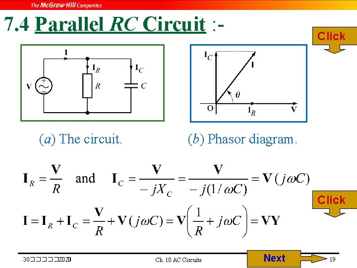
Phasor Diagram Of Rc Parallel Circuit. The relationship between the voltage and currents in a parallel rc circuit is illustrated in the vector (phasor) diagram of figure 2and summarized as follows: Applying kvl at the rlc circuit, we will get the following equation.
UNIT7 AC Circuits Ch 10 AC Circuits Next from slidetodoc.com
Since the current through the resistor. In a parallel rc circuit: The relationship between the voltage and currents in a parallel rc circuit is illustrated in the vector (phasor) diagram of figure 2and summarized as follows:
Web Vector Diagram For A Parallel Rc Circuit By Terry Bartelt Learners Read About The Vector Diagram For A Parallel Rc Circuit.
Web the phasor diagram for a parallel rlc circuit is produced by combining together the three individual phasors for each component and adding the currents vectorially. The figure below shows a composite diagram of the circuit conditions. Vs = vr + vl + vc.
The Relationship Between The Voltage And Currents In A Parallel Rc Circuit Is Illustrated In The Vector (Phasor) Diagram Of Figure 2And Summarized As Follows:
How to draw a vector diagram draw a vector of admittance of resistor. Web the rc series circuit is shown in the figure below: Since the current through the resistor.
The Ac Supply Is Given By, V = Vm Sin Wt.
Web the figure above illustrates a parallel rc circuit. Web in this class, fundamentals of parallel rc circuit have been discussed clearly with phasor diagram.parallel rc circuitparallel cr circuitparallel rc circuit. Web this video contains phasor diagram and different parameters like impedance angle or phase angel, power factor, quality factor and dissipation factor of rc parallel circuit.
Consider A Circuit In Which R, L, And C Are Connected In Series With Each Other Across Ac Supply As Shown In Fig.
Web these two components are now in parallel. The current phasors i r and i c are out of phase,. Applying kvl at the rlc circuit, we will get the following equation.
Determine The Voltages Across And The Currents.
An ac generator produces an emf of amplitude 10 v at a frequency f = 60hz. As with series rc circuits, the techniques used with other. Web the vector diagram of the admittance of the rc parallel circuit can be drawn in the following steps.